Howdy guys!
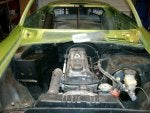
About two weeks ago I got a 1973 Opel GT from another member here in Georgia and started the restoration process. The vehicle is strip down to bare essentials and the conversion process to a convertible will start soon. I have named this project "Stealth" since the vehicle will be painted flat black and most accents will be in red. Of course a flat black GT convertible will stick out like a sore thumb but I kinda like the name.
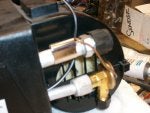
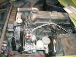
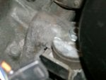
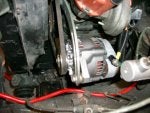
The engine on this vehicle had a bent valve which I took care of and during the repair process, I grooved the chambers as per an article I read here in the forum and information from the Somerden Singh web site. After all, the mod is not that intrusive and I did not see any harm to the head. I also installed a different carburetor using an aluminum interface plate and a phenolic 1/2" spacer, a 45mm single barrel Carter (190Cfm) I had laying around since the Solex was locked up inside.
I was amazed at the end result. The engine idles smoothly from 475 Rpm to 900 Rpm and the reaction time on acceleration is quite superior and almost instant with only the stock mechanical advance. There was no vibration at very low RPM's and even the exhaust smell was totaly different. Water temperature never exceeded 180 degrees on any of the three 15 minute runs. Needless to say, I will be keeping the Opel engine on this build.
This vehicle will get a few upgrades which I will be posting as the work progresses. The main points will be 4-wheel disk brakes, master cylinder and booster relocation, better (lighter) cooling system, power windows and locks, power convertible top and air conditioning.
The work plan is being developed at this time and work should commence after the final design has been completed.
As always, any and all suggestions will be appreciated.
About two weeks ago I got a 1973 Opel GT from another member here in Georgia and started the restoration process. The vehicle is strip down to bare essentials and the conversion process to a convertible will start soon. I have named this project "Stealth" since the vehicle will be painted flat black and most accents will be in red. Of course a flat black GT convertible will stick out like a sore thumb but I kinda like the name.
The engine on this vehicle had a bent valve which I took care of and during the repair process, I grooved the chambers as per an article I read here in the forum and information from the Somerden Singh web site. After all, the mod is not that intrusive and I did not see any harm to the head. I also installed a different carburetor using an aluminum interface plate and a phenolic 1/2" spacer, a 45mm single barrel Carter (190Cfm) I had laying around since the Solex was locked up inside.
I was amazed at the end result. The engine idles smoothly from 475 Rpm to 900 Rpm and the reaction time on acceleration is quite superior and almost instant with only the stock mechanical advance. There was no vibration at very low RPM's and even the exhaust smell was totaly different. Water temperature never exceeded 180 degrees on any of the three 15 minute runs. Needless to say, I will be keeping the Opel engine on this build.
This vehicle will get a few upgrades which I will be posting as the work progresses. The main points will be 4-wheel disk brakes, master cylinder and booster relocation, better (lighter) cooling system, power windows and locks, power convertible top and air conditioning.
The work plan is being developed at this time and work should commence after the final design has been completed.
As always, any and all suggestions will be appreciated.